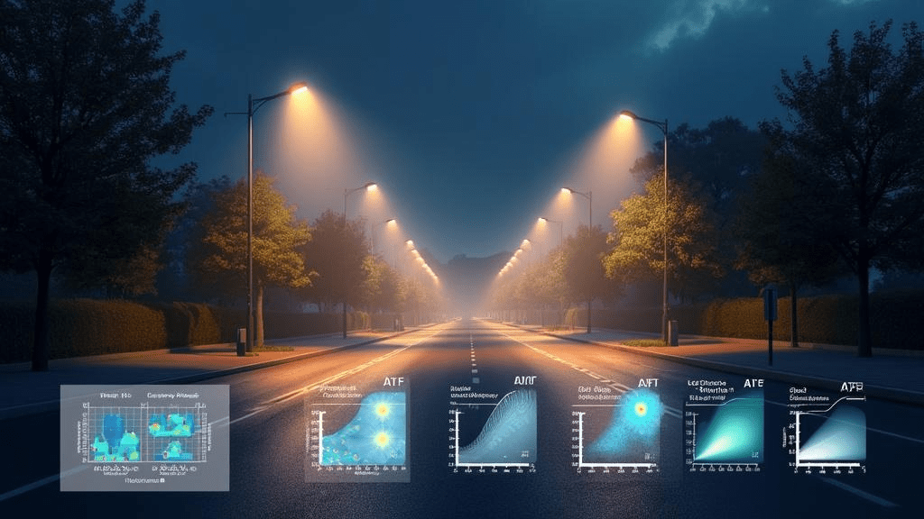
LED Street Lighting Design Guide: How to Achieve EN 13201 Compliance
What it covers: Luminance classes (M/ME), uniformity, TI thresholds, maintenance factor, validation steps. Target: “LED street lighting”, “EN 13201 compliance”.
LED Street Lighting Design Guide:
How to Achieve EN 13201 Compliance
If you are planning or upgrading LED street lighting, EN 13201 is the European benchmark for safety, visual performance, and energy efficiency. Getting it right is not just about picking a wattage and a pole height. It’s about the right lighting class, the right optics, correct maintenance factors, and proper verification on site. This guide walks you through a practical, real-world workflow we use on projects to design, document, and validate EN 13201-compliant road lighting.
Why EN 13201 matters
Fewer crashes and complaints: Correct luminance, uniformity, and glare control.
Lower bills: Put light where it’s needed with the right optics and dimming.
Clear paperwork: Defensible compliance for authorities and asset managers.
Pick the right lighting class (M, C, P)
M (motorized): Luminance-based for through-roads and higher speeds.
C (conflict): Illuminance-based for junctions/roundabouts.
P (pedestrian/cyclist): Illuminance-based for local streets and paths.
Quick selector:Higher speed/steady flow → M1–M4;
Lower speed/local access → M5–M6 or P.
Complex nodes/crossings → C (even if approaches are M).
Heavy pedestrian/CCTV needs → P or C.
Targets in short:M classes: Lavg ≈ 0.30–2.0 cd/m², Uo ≥ 0.35–0.40, Ul ≥ 0.50–0.70, TI ≤ 10–15%, SR ≥ 0.5.
P classes: 2–15 lx, Uo ≥ 0.25–0.40 (maintained values).
Know the metrics that drive compliance
Lavg: average road luminance (M classes).
Uo: overall uniformity (Lmin/Lavg).
Ul: longitudinal uniformity along the driving line.
TI: disability glare; must be at/below the class limit.
SR: surround ratio for peripheral vision.
For P/C: horizontal (and where needed, vertical) illuminance and Uo.
Set the road surface (R-table)
Pick R1–R4 to match pavement reflectance (fresh vs aged asphalt matters).
No survey? Use a local default (often R3) and document it.
Wrong R-table can force over-lighting or fail uniformity.
Match optics and layout to the geometry
Distribution: long/narrow beams for single-sided; broader for staggered/median.
Mounting height: 6–12 m typical; higher improves uniformity, increases structure cost.
Spacing/height ratio: aim ~3.5–5.0 as a first pass for M roads.
Keep tilt minimal; use shields to cut spill to houses.
Design with a realistic Maintenance Factor (MF)
MF = LLMF × LSF × LMF.
Example: 0.90 × 0.98 × 0.90 ≈ 0.79. Never assume MF = 1.00.
Base LLMF/LSF on LM-80/TM-21 and real cleaning cycles for the site.
Model it properly
Use DIALux evo, Relux, or AGi32 with current IES/LDT files.
Draw exact geometry (carriageway, verge, median) and set MF, R-table, observer.
M-class: luminance grids per EN 13201-3; P/C: horizontal (and vertical if relevant).
Try single-sided, opposite, and staggered; track TI with each change.
Keep glare under control (TI)
Choose true cut-off optics with low high-angle intensity.
Avoid over-tilt; increase height or setback if TI is tight.
Warmer CCT can help comfort, but optical control matters more.
Design for dark-sky and neighbors
Target ULOR ≈ 0% (flat glass/full cut-off).
Prefer ≤3000 K near residences and habitats.
Check BUG/backlight and add shields at boundaries.
Validate on site (EN 13201-4)
Dry pavement, dark sky, correct dimming level.
Measure luminance/illuminance on the standard grid; compute Uo/Ul properly.
Calculate TI from installed geometry; respect tolerances and document.
Prove the energy case (EN 13201-5)
Report AECI (kWh/year) with the real dimming schedule.
Example profile: 100% to 22:00, 70% to 01:00, 50% to 05:00, then 100%.
Use D4i/DALI-2 drivers for easy control and verification.
Deliver clean documentation
Class selection rationale, inputs (R-table, MF), and results (Lavg/Uo/Ul/TI or Em/Uo).
Layouts: pole positions, heights, outreach, tilt; luminaire schedule (optic, CCT/CRI, controls).
AECI summary, dimming profile, maintenance plan, and field verification.
Record any as-built changes.
Common pitfalls (and fixes)
Wrong R-table or outdated photometry → verify surface and files; document assumptions.
MF = 1.00 → use evidence-based LLMF/LSF/LMF; design to maintained values.
“Fixing” uniformity with tilt → switch optics or layout; keep tilt low to control TI.
Ignoring TI → track glare at every iteration, not just at the end.
Raw LED lumens vs luminaire lumens → size by luminaire output and real drive current.
Copy-pasted spacings → recheck S/H for each road width/height.
Skipping SR/vertical checks → include adjacent areas and vertical illuminance where faces matter.
No field plan or as-built record → schedule EN 13201-4 and update the handover pack.
Quick checklist
Select class (M/C/P) via risk assessment.
Set R-table, MF, observer before iterations.
Pick optic/layout; iterate spacing/height/offset with Lavg/Uo/Ul/TI/SR in view.
Confirm IP/IK, surge protection, control protocol, and dimming profile.
Validate ULOR/BUG and appropriate CCT.
Compute AECI; align with energy/CO2 targets.
Plan cleaning/inspection; justify MF.
Book EN 13201-4 measurements; finalize as-built documents.
Conclusion
Get the fundamentals right early—class, MF, optics, and verification—and you’ll deliver safer roads with lower energy and fewer complaints. Want a sanity check before tender? Share your layout and assumptions; we’ll return a lean, compliant alternative within 24 hours.


